Linux卡片电脑
一、Hardware
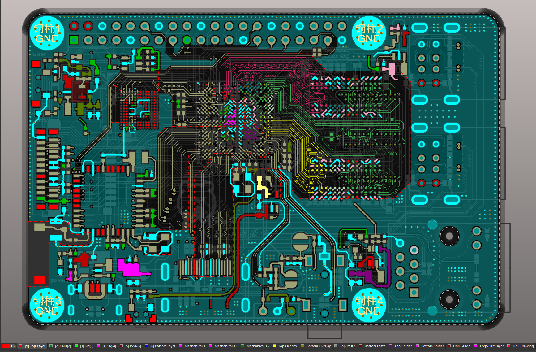
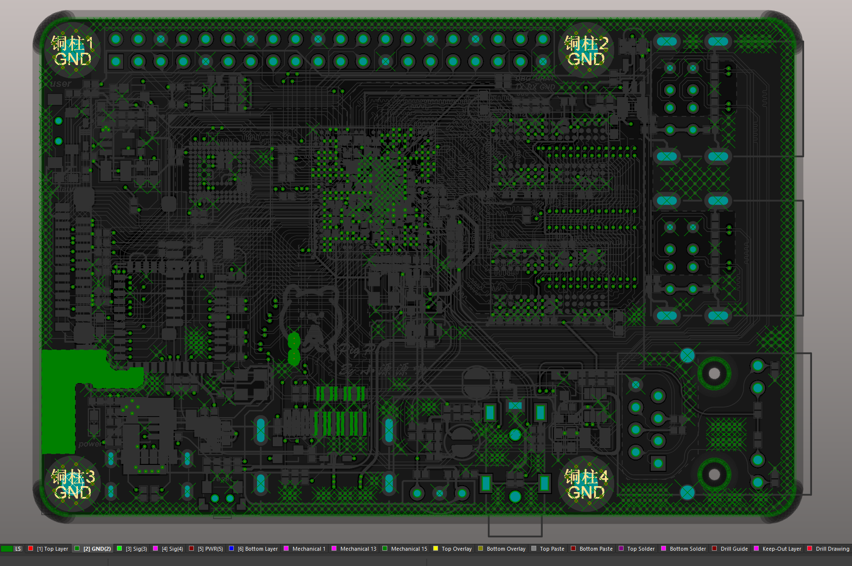
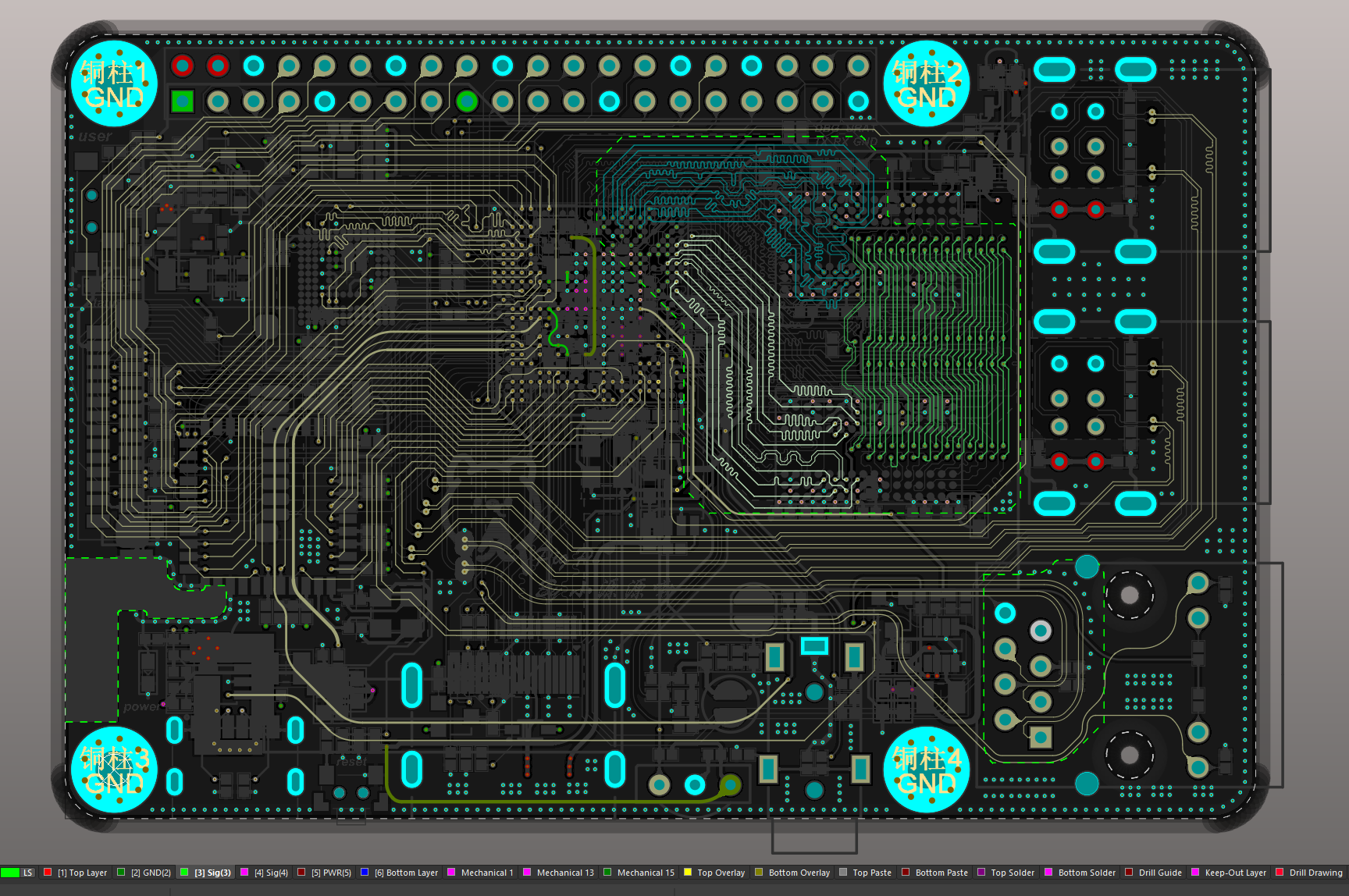
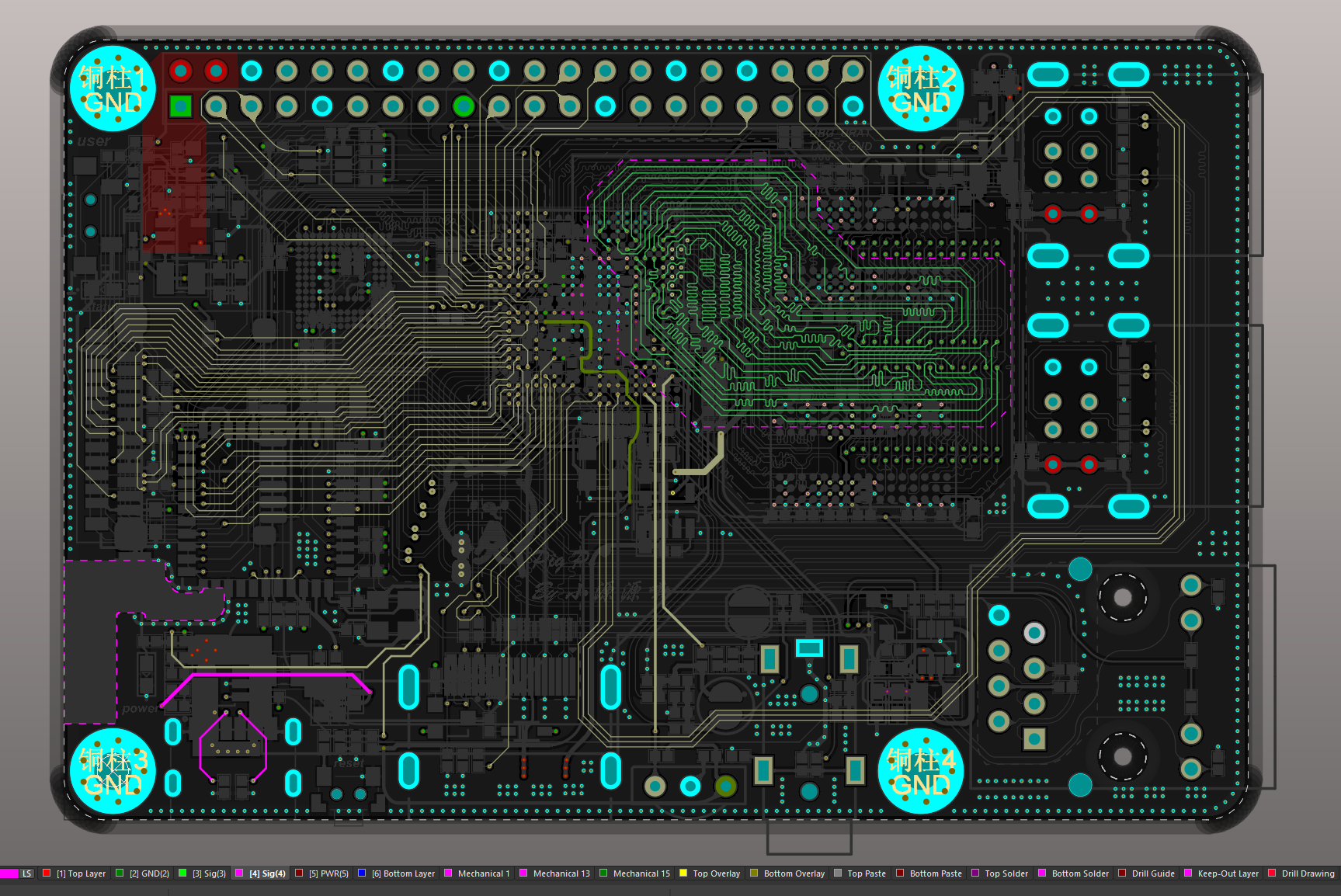
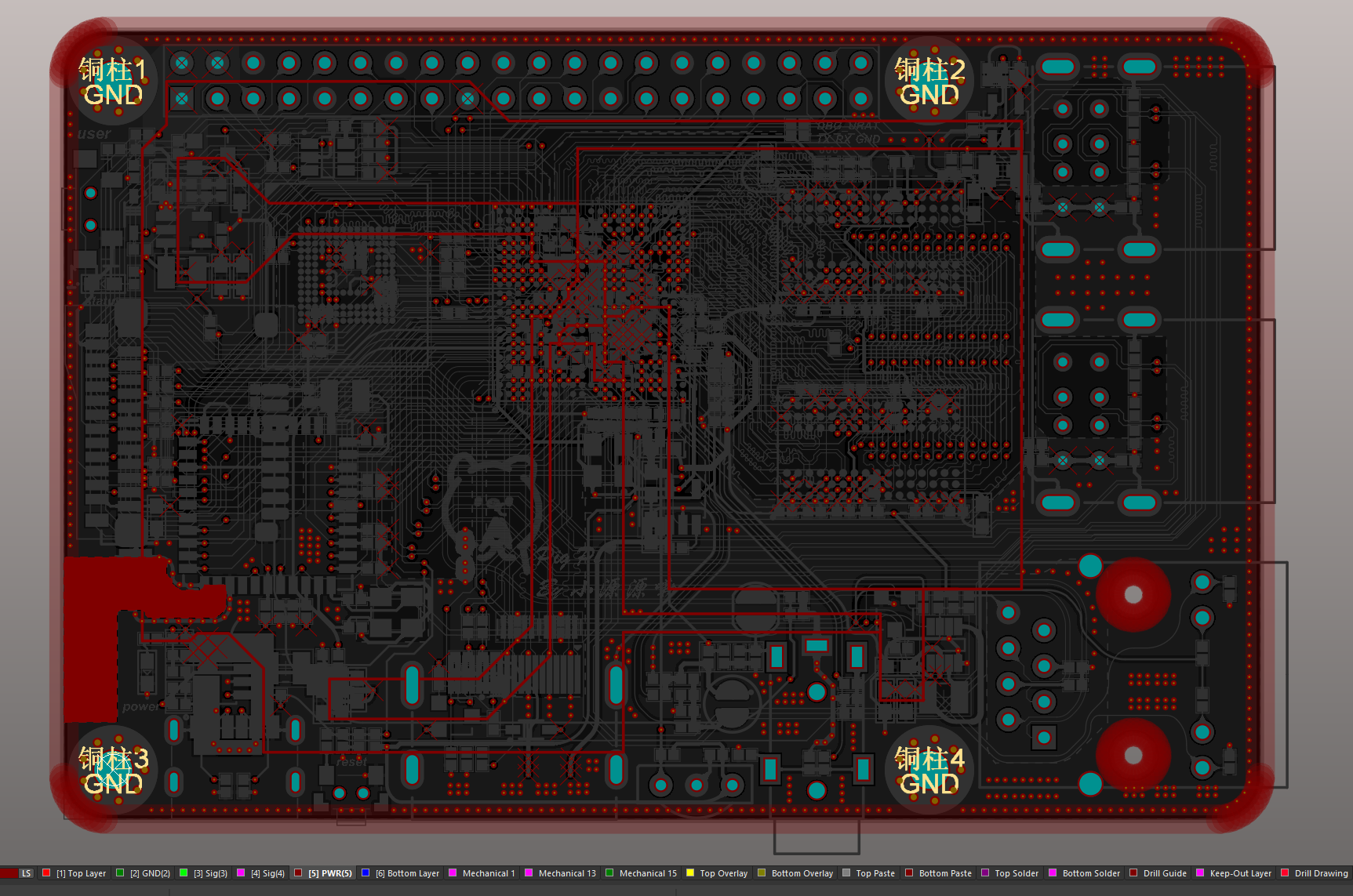
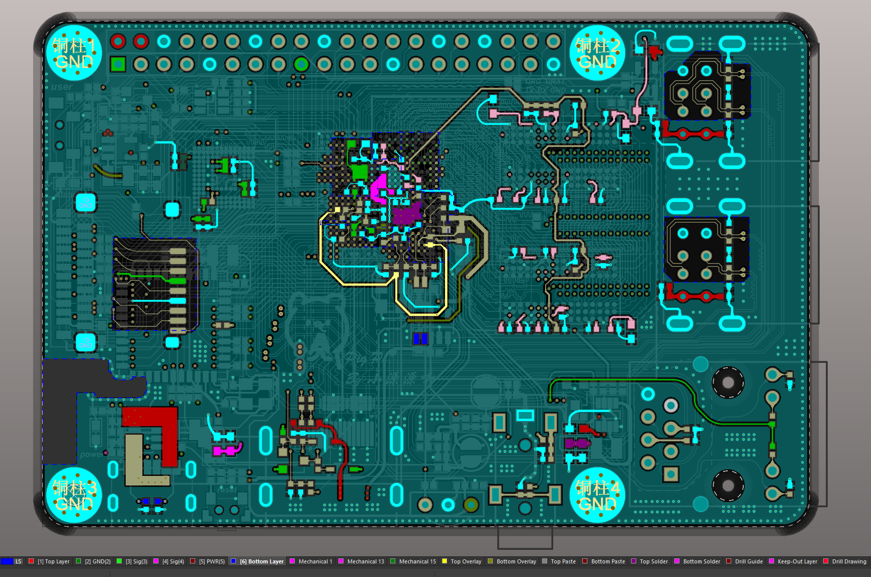
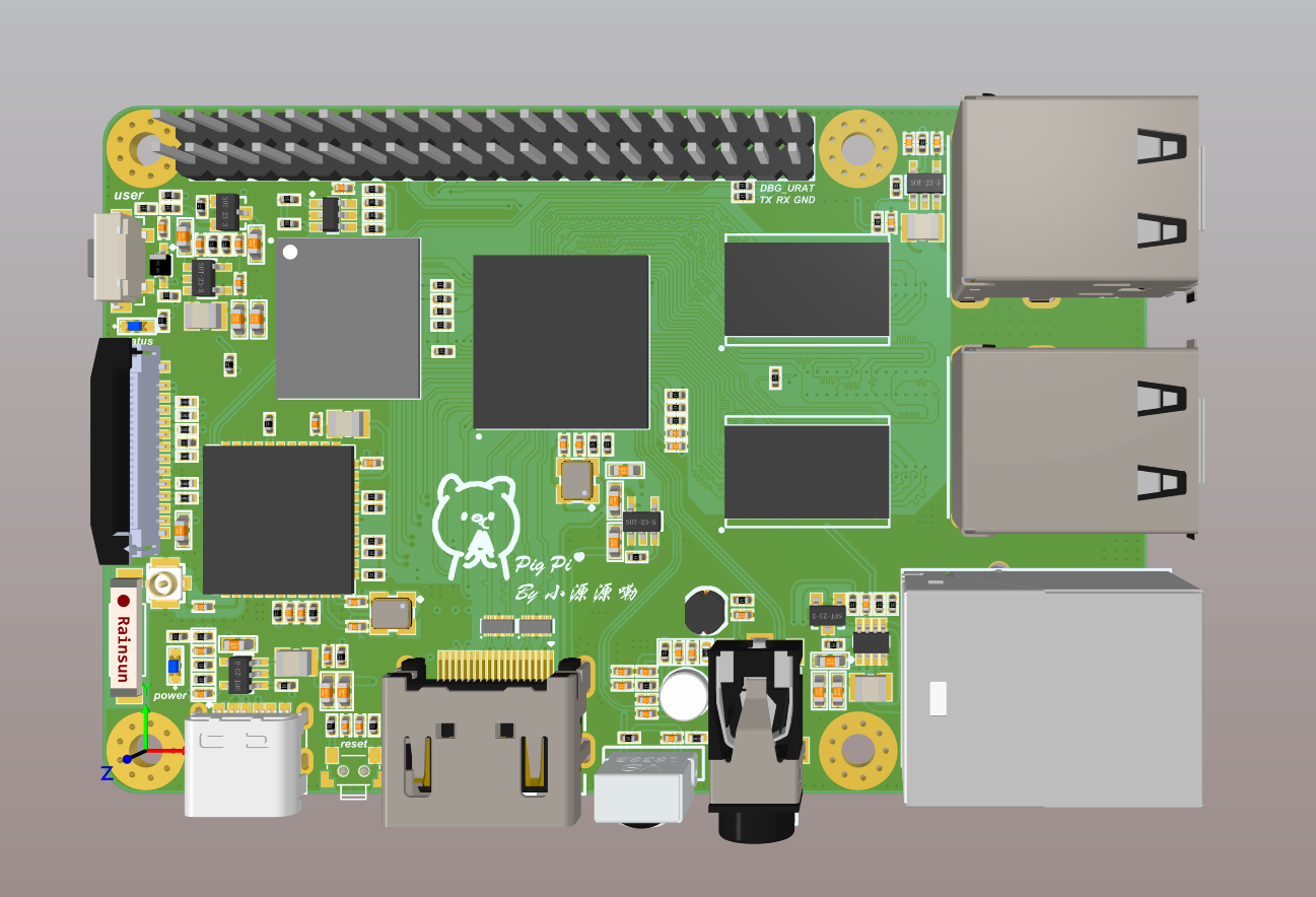
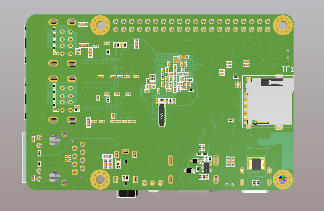
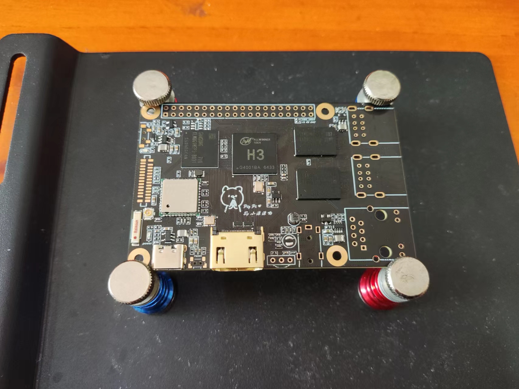
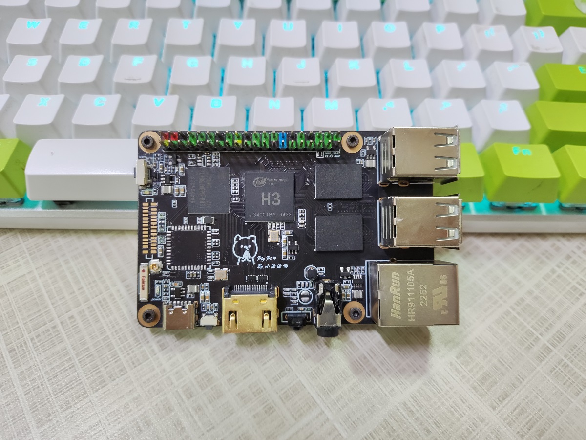
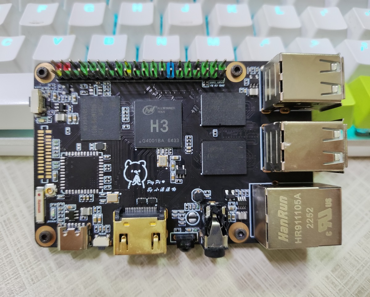
1.1 整体框图
- Top1层
- Gnd2层
- Sig3层
- Sig4层
- Power5层
- Bottom6层
- 3D视图
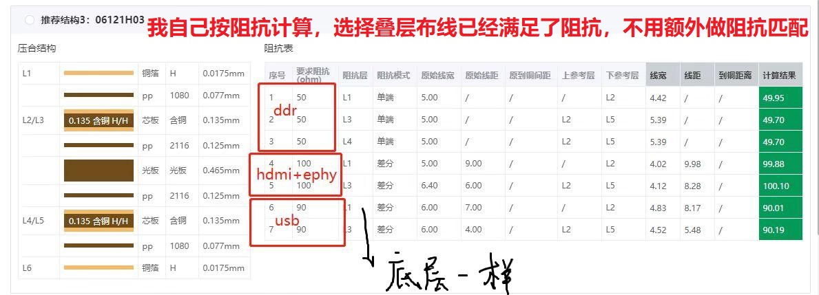
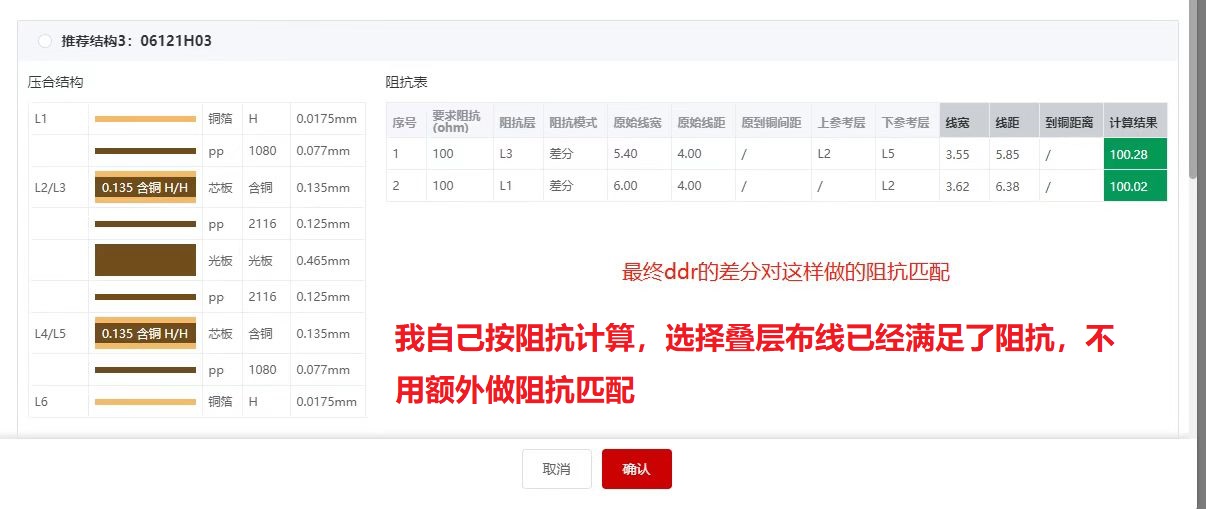
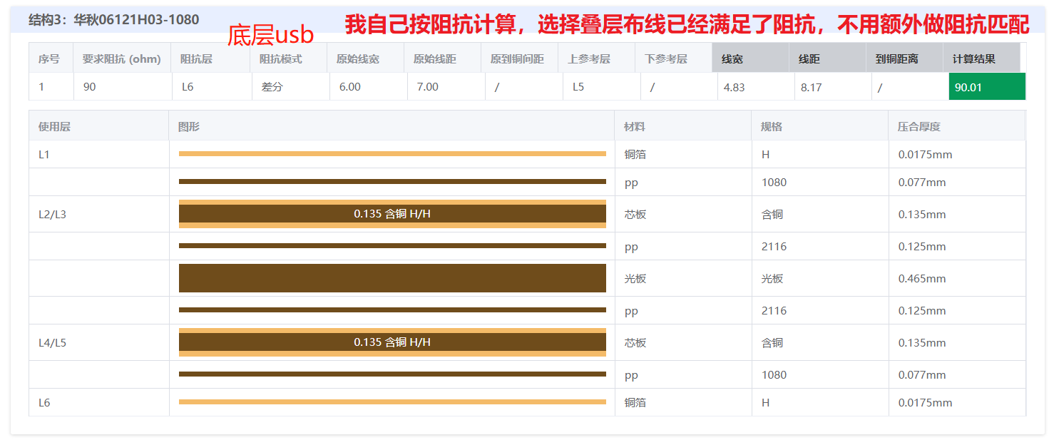
1.2 阻抗匹配
1.3 手工焊接
1.4 DDR3位宽说明
K4B4G1646B 4Gbit 256M x 16bit内存芯片,A0~A14用做行地址,A0~A9用做列地址,这款芯片同时含有B0~B2用来选择bank。bank address有三个bit,所以单个16bit DDR3内部有8个bank。
- 表示行的有A0~A14,共15个bit,说明一个bank中有2^15个行。
- 表示列的有A0~A9, 共10个bit,说明一个bank中有2^10个列。
- 所以单块16bit DDR3可以寻址2^32^152^10=2^28=256M个地址。
- 我们的位宽是16bit,也即访问一个地址,内存认为是访问16bit的数据,所以单个内存颗粒的容量为512M Bytes
我们的H3用两片16bit的K4B4G1646B拼成了一个32bit位宽、总容量为1G Bytes的内存:
- 第一片16bit DDR3的BA0, BA1, BA2连接到了CPU的BA0, BA1, BA2。
- 第二片16bit DDR3的BA0, BA1, BA2也连接到了CPU的BA0, BA1, BA2。
- 第一片16bit DDR3的A0~A14连接到了CPU的A0~A14。
- 第二片16bit DDR3的A0~A14连接到了CPU的A0~A14。
- 第一片16bit DDR3的D0~D15连接到了CPU的D0~D15。
- 第二片16bit DDR3的D0~D15连接到了CPU的D16~D31。
再来看看两个16bit是如何组成一个32bit的。这儿所说的两个16bit组成一个32bit,指的是数据位宽,与地址没有关系。
每一块16bit DDR3中有8个bank,2^15个row,2^10个column。也就是有256M个地址。看前面的连线可知,两块16bit DDR3的BA0BA2和A0\A14其实是并联连接到CPU,也就是说,CPU其实认为只有一块内存,访问的时候按照BA0~BA2和A0~A14给出地址。
CPU发出地址,两块16bit DDR3都收到了该地址。要么将给定地址上2个字节送到数据线上,要么是将数据线上的两个字节写入到指定的地址。
再看数据线的连接,第一片的D0~D15连接到了CPU的D0~D15,第二片的D0~D15连接到了CPU的D16~D31。CPU认为自己访问的是一块32bit的内存,所以CPU每给出一个地址,将访问4个字节的数据,读取/写入。这4字节数据对应到CPU的D0~D31,又分别被连接到两片内存的D0~D15,这样一个32bit就被拆成了两个16bit,也就是两个16bit组成了一个32bit。
CPU可访问的内存地址有256M个,每访问一个地址,将访问4个字节,这样CPU能访问的内存即为256M x 32bit = 1G Bytes
原理图可以看到我们的CPU的A15接到了K4B4G1646B的M7,但实际上M7是NC,我们A15接上去是为了兼容大容量的有A15地址线的ddr3,同时ddr3的ODT1,CS1#,CKE1,ZQ1都不接,我们的K4B4G1646B对应的引脚J1 L1 J9 L9都是NC,方便布线就不接了,其他的ddr3有些用到了这几个引脚,也即他们不是NC,所以省略不接的缺陷就是不能兼容其他的ddr3,我们这里就用K4B4G1646B颗粒,不接没事。
二、系统移植
2.1 安装交叉编译器
①下载交叉编译器arm-cortexa9-linux-gnueabihf-4.9.3.tar.xz,然后解压编译器:
1 | mkdir -p /opt/YuanPi-Plus/toolchain |
②将编译器的路径加入到PATH中,vi ~/.bashrc,在末尾加入以下内容:
1 | export PATH=/opt/FriendlyARM/toolchain/4.9.3/bin:$PATH |
③这个编译器是64位的,不能在32位的Linux系统上运行,安装完成后,验证是否安装成功:
1 | arm-linux-gcc -v |
2.2 编译适配U-boot
①下载U-boot源码,并切换分支:
1 | git clone https://github.com/friendlyarm/u-boot.git -b sunxi-v2017.x --depth 1 |
②安装Python库:
1 | apt-get install swig python-dev python3-dev |
③使用nanopi_h3_defconfig配置:
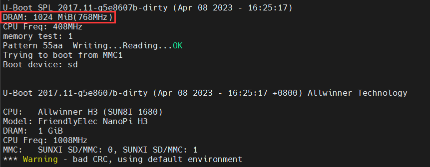
1 | 修改DDR3频率为768M,经过测试我的硬件最大支持这个频率 |
④编译U-boot:
1 | make ARCH=arm CROSS_COMPILE=arm-linux- -j12 |
⑤更新SD上的U-boot:
1 | dd if=u-boot-sunxi-with-spl.bin of=/dev/sdX bs=1024 seek=8 |
⑥SD卡运行系统时,可以先用scp命令拷贝u-boot-sunxi-with-spl.bin到开发板上,然后用dd命令更新SD卡上的U-boot:
1 | scp u-boot-sunxi-with-spl.bin root@192.168.31.134:/root/ |
⑦成功效果如下:
2.3 编译适配Linux内核
①下载Linux内核源码,并切换分支:
1 | git clone https://github.com/friendlyarm/linux.git -b sunxi-4.14.y --depth 1 |
②默认配置先跑起来:
1 | apt-get install u-boot-tools |
③更新SD上的zImage和dtb文件:假设SD卡的boot分区挂载在/media/SD/boot/
1 | cp arch/arm/boot/zImage /media/SD/boot/ |
④bootargs与bootcmd:全志H3使用boot.cmd生成boot.scr来描述配置,boot.cmd:
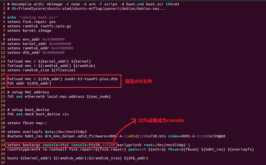
1 | Recompile with: mkimage -C none -A arm -T script -d boot.cmd boot.scr CPU=H3 |
boot.cmd –> boot.scr:将boot.scr也放入SD卡的/boot中即可
1 | mkimage -C none -A arm -T script -d boot.cmd boot.scr CPU=H3 |
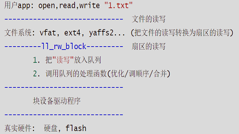
2.4 文件系统
①文件系统解压到SD卡:
1 | sudo tar -xvf rootfs.tar -C /media/qing/rootfs/ |
②编译和更新驱动模块:更新SD卡上rootfs的驱动模块:
1 | make modules ARCH=arm CROSS_COMPILE=arm-linux- |
make modules_install命令的作用是:
- 将编译好的内核模块从内核源代码目录copy到/lib/modules下。也可自己指定ko安装路径,在交叉编译的情况下,需要将ko模块安装到rootfs。也即:INSTALL_MOD_PATH=/media/SD/rootfs/。
- 运行modules_install的另一个作用是会运行depmod去生成modules.dep文件,该文件记录了模块之间的依赖关系。这样当modprobe XXX的时候就能够把XXX所依赖的模块一并加载了。
2.5 Wifi模块驱动
如果是江师兄和稚晖君的版本,他们使用的是RTL8723bu,友善之臂的linux工程没有RTL8723bu驱动,我目前使用的是稚晖君基于友善之臂添加后的linux工程,RTL8723bu驱动代码放在了:drivers/net/wireless/realtek/rtl8723bu,并且稚晖君的配置文件:linux_card_defconfig已经使能了该驱动,编译linux工程会将RTL8723bu编译成模块。这份驱动代码会依赖其他的一些驱动,所以按照上一节操作,将驱动导出到rootfs,然后:
1
2wifi驱动的目录:/lib/modules/4.14.111/kernel/drivers/net/wireless/realtek/rtl8723bu
装rtl8723bu驱动的时候先depmod一下,再modprobe,下次开机会自动装载。如果是友善之臂的h3 M1 Plus,或者是我做的版本,使用的是AP6212,友善之臂已经适配了ap6212;YuanPi-plus-defconfig配置是我基于友善之臂的sunxi_defconfig修改的,直接使用我修改后的配置编译出的zImage启动即可。当然,也有可能ap6212驱动代码不在linux工程中,是友善之臂的文件系统里面有适配好的ko文件,然后启动时脚本自动装载了,具体代码或者ko文件是啥我没去找过,能用就行。
不管是稚晖君还是我的设备树,都是友善之臂的复制过来修改的,所以设备树没有区别,区别只在配置文件和有无RTL8723bu驱动代码。RTL8723bu是usb wifi,ap6212是sdio接口,他们可以共存。
连接wifi
1
2
3
4
5
6
7
8
9
10
11
12
13
14
15
16
17
18开启Wi-Fi:
nmcli r wifi on
扫描附近的Wi-Fi:
nmcli dev wifi
连接到特定的Wi-Fi:
nmcli dev wifi connect "SSID" password "PASSWORD" ifname wlan0
重启网卡设备:
sudo ifconfig wlan0 down
sudo ifconfig wlan0 up
连接成功后,下次开机,WiFi 也会自动连接。
如果你的USB WiFi无法正常工作, 大概率是因为文件系统里缺少了对应的USB WiFi固件。
可以通过下列命令安装所有的USB WiFi固件:
apt-get install linux-firmware
2.6 nfs网络文件系统
- ubuntu先安装nfs服务:apt-get install nfs-kernel-server rpcbind
- 配置相关文件夹为nfs文件夹:vi /etc/exports
- 在最后一行加上文件夹路径:/home/qing/work/nfs/rootfs_friendlycore-focal_4.14 *(rw,sync,no_root_squash)
- 然后重启ubuntu服务:/etc/init.d/nfs-kernel-server restart
- 被挂载的文件夹最好 :chmod 777 xxx/
- 在开发板里面也要安装nfs服务:apt-get install nfs-kernel-server rpcbind
- 重启开发板的nfs服务:/etc/init.d/nfs-kernel-server restart
- 挂载:mount -t nfs ubuntu-IP:/home/qing/work/nfs/rootfs_friendlycore-focal_4.14/ /mnt/ -o nolock
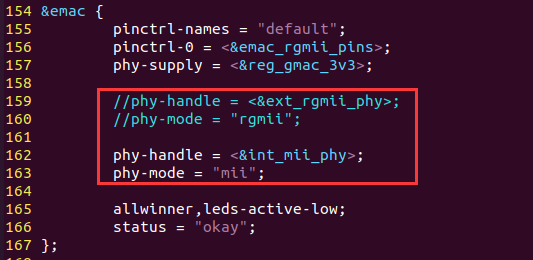
参考OrangePi,以太网要修改sun8i-h3-YuanPi-plus.dts:因为友善M1-Plus用了RTL8211E,我们是直连的。
三、软件适配
3.1 st7789v彩屏(SPI)
Frame Buffer设备驱动在另一篇文章已经讲解,这里直接在内核自带的fbtft框架上修改。
3.1.1 修改设备树
①首先复制一份sun8i-h3-nanopi-m1-plus.dts重命名为sun8i-h3-YuanPi-plus.dts,并修改设备树目录下的Makefile加上我们的设备树。最后在sun8i-h3-YuanPi-plus.dts中添加:
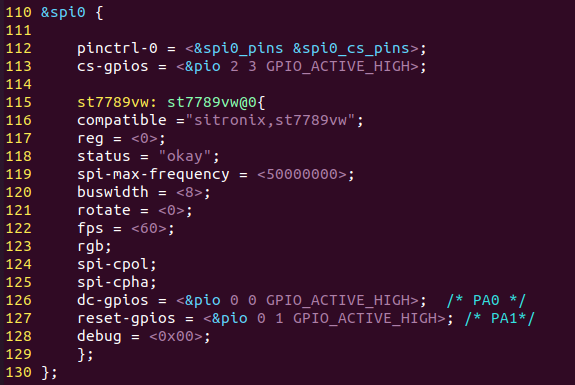
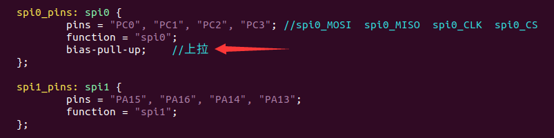
1 | &spi0 { |
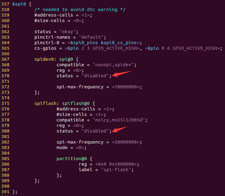
②修改sun8i-h3-nanopi.dtsi,将spi0结点下的设备都disabled:
3.1.2 修改kernel
①make menuconfig使能fbtft框架,并勾选fb_st7789vw.c:
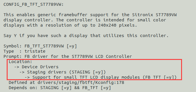
1 | Device Drivers ---> |
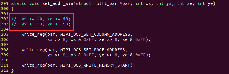
②修改drivers/staging/fbtft/fb_st7789vw.c:
我们的屏幕不需要偏移,将偏移去除:
修改分辨率:
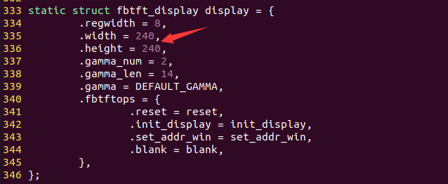
最后修改初始化代码:将init_display(struct fbtft_par *par)中初始化代码换成当下屏幕的即可。
3.1.3修改bootargs
修改boot.cmd –> boot.scr,让屏幕作为console:

1 | fatload mmc 0 ${dtb_addr} sun8i-h3-YuanPi-plus.dtb |
3.1.4 编译烧录找bug
编译出zImage、sun8i-h3-YuanPi-plus.dtb、boot.scr,重新烧录后发现屏幕不起作用,但是在启动阶段发现有微弱的闪动,开启找bug之旅。。。
首先怀疑屏幕坏了,毕竟买了挺久了,用之前Frame Buffer设备驱动的程序在RK3399上测试,屏幕正常。
去掉fbtft框架,用以前自己写的Frame Buffer设备驱动的程序测试,还是只有微弱的闪光,那么问题应该是出在spi驱动能力上,给SCK时钟线接一个3.3v,2.2k上拉,再次实验,成功了。重新加上fbtft框架编译烧录即可。注:这也不是板子硬件bug,将来屏幕转接板上拉即可,同时要注意上拉的电流不能太大,不然时间久了会烧屏。
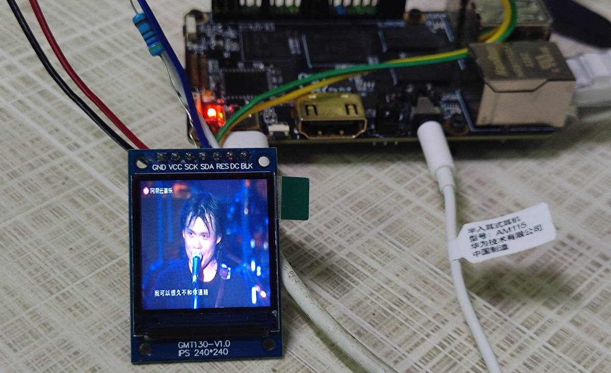
经过多次测试,spi频率最大能到72M;此时SCK接的是3.3v,10k上拉,频率为50M,最终效果如下:
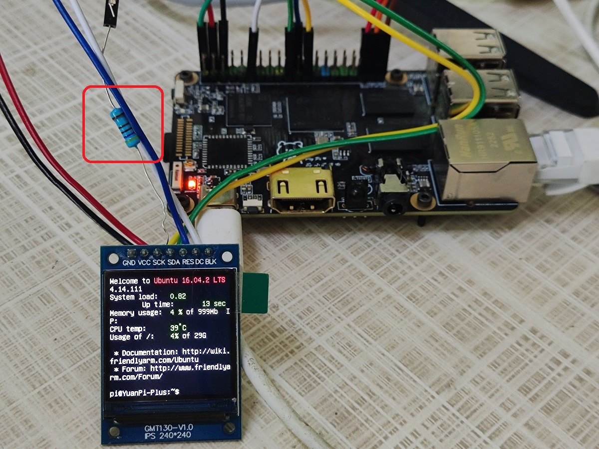
最终发现不用外接上拉电阻,直接将spi0配置成上拉模式即可,并且spi频率也可以设置为72M,96M不行,屏幕大。
3.1.5 音视频播放
①安装mplayer:
1 | apt-get install mplayer |
②安装alsa包:
1 | apt-get update |
③播放视频:
1 | mplayer -ao alsa -vo fbdev:/dev/fb_st7789vw -x 240 -y 240 -zoom 被动-伍佰.mp4 |
④alsamixer可以调节音量,声音太大到了高潮部分功率上不去会卡死。
⑤爱伍佰,做他一半就好……
3.2 GT911电容触摸(IIC)
3.2.1 修改设备树
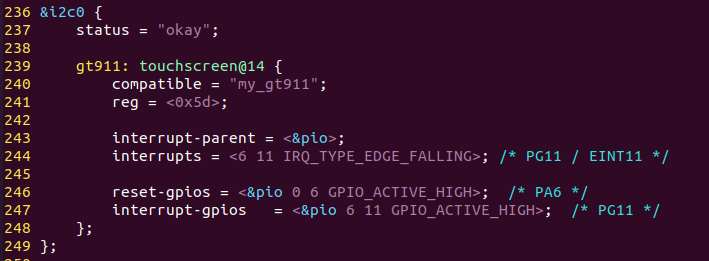
GT911使用的是IIC接口,可以设置中断模式,当有触摸动作则会触发中断,在中断中读取寄存器信息,通过input上报坐标,因为板子上的i2c0在硬件上已经上拉,所以设备树不用上拉,修改设备树如下:sun8i-h3-YuanPi-plus.dts
3.2.2 编写驱动
电容触摸屏驱动其实就是以下几种 linux 驱动框架的组合:
- IIC 设备驱动,因为电容触摸 IC 基本都是 IIC 接口的,因此大框架就是 IIC 设备驱动。
- 通过中断引脚(INT)向 内核上报触摸信息,因此需要用到中断驱动框架。坐标的上报在中断服务函数中完成。
- 触摸屏的坐标信息、屏幕按下和抬起信息都属于input 子系统,因此向内核上报触摸屏坐标信息就得使用 input 子系统。只是我们得按照 linux 内核规定的规则来上报坐标信息。
以上内容在前面的博文已有介绍,不再赘述,在实际驱动GT911需要注意如下几点:
- 与其他的IIC设备不同,GT911的器件地址需要根据初始化时序来确定,地址确定后才能用i2cdetect检测出地址。
- 当输出中断后请在一个中断周期内读走坐标并将buffer status(0x814E)写为0,若未在中断内读走坐标,下次IC即使检测到坐标更新会再输出一个中断脉冲,但不更新坐标,如果一直没有读取坐标则会一直打脉冲,导致中断一直被触发。
- 我们的屏幕进行了旋转,所以读取出来的坐标也需要在软件上进行调整,如下:
1
2
3
4
5
6
7
8我们的屏幕旋转了90度,对应如下:
原先 --> 旋转后
(0,0) --> (0,240)
(240,0) --> (0,0)
(0,320) --> (320,240)
(240,320) --> (320,0)
所以对应的调整关系是:
(X,Y) --> (Y,|X-240|)
完整代码如下所示,相应注释已给出:
1 |
|
3.2.3 移植tslib
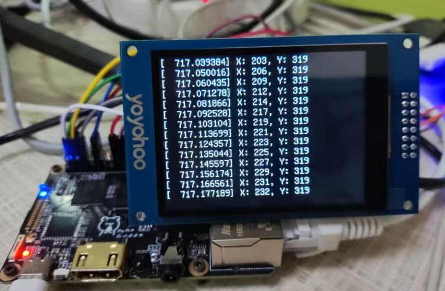
首先装载gt911驱动,自己的驱动成功效果如下:
tslib 是一个开源的第三方库,用于触摸屏性能调试,使用电阻屏的时候一般使用 tslib 进行校准。虽然电容屏不需要校准,但主要的是 tslib 提供了一些其他软件,我们可以通过这些软件来测试触摸屏工作是否正常。最新版本的 tslib 已经支持了多点电容触摸屏,因此可以通过 tslib 来直观的测试多点电容触摸屏驱动,这个要比观看 eventX 原始数据方便的多。
①获取tslib源码。git 地址为:https://github.com/kergoth/tslib ,目前最新的版本是1.21。
②修改 tslib 源码所属用户,修改解压得到的 tslib-1.21 目录所属用户为当前用户,这一步一定要做!否则在稍后的编译中会遇到各种问题。我当前 ubuntu 的登录用户名为“qing”,修改命令如下:
1 | sudo chown qing:qing tslib-1.21 -R |
③ubuntu工具安装:
1 | sudo apt-get install autoconf |
④编译tslib:编译完成后在安装目录中,bin 目录下是可执行文件,包括 tslib 的测试工具。etc 目录下是 tslib 的配置文件,lib目录下是相关的库文件,将所有文件拷贝到开发板中。
1 | ./autogen.sh |
⑤配置tslib
- 打开etc/ts.conf 文件,找到module_raw input,如果这句前面有“#”的话就删除掉“#”。
- 在开发板终端输入:
1
2
3
4
5
6
7注意,下面路径是根目录,如果没有这些文件,运行时会生成
export TSLIB_TSDEVICE=/dev/input/event2
export TSLIB_CALIBFILE=/etc/pointercal
export TSLIB_CONFFILE=/etc/ts.conf
export TSLIB_PLUGINDIR=/lib/ts
export TSLIB_CONSOLEDEVICE=none
export TSLIB_FBDEVICE=/dev/fb1
⑥ tslib 测试:使用ts_test_mt来测试触摸屏工作是否正常,测试结果如下,一切正常:
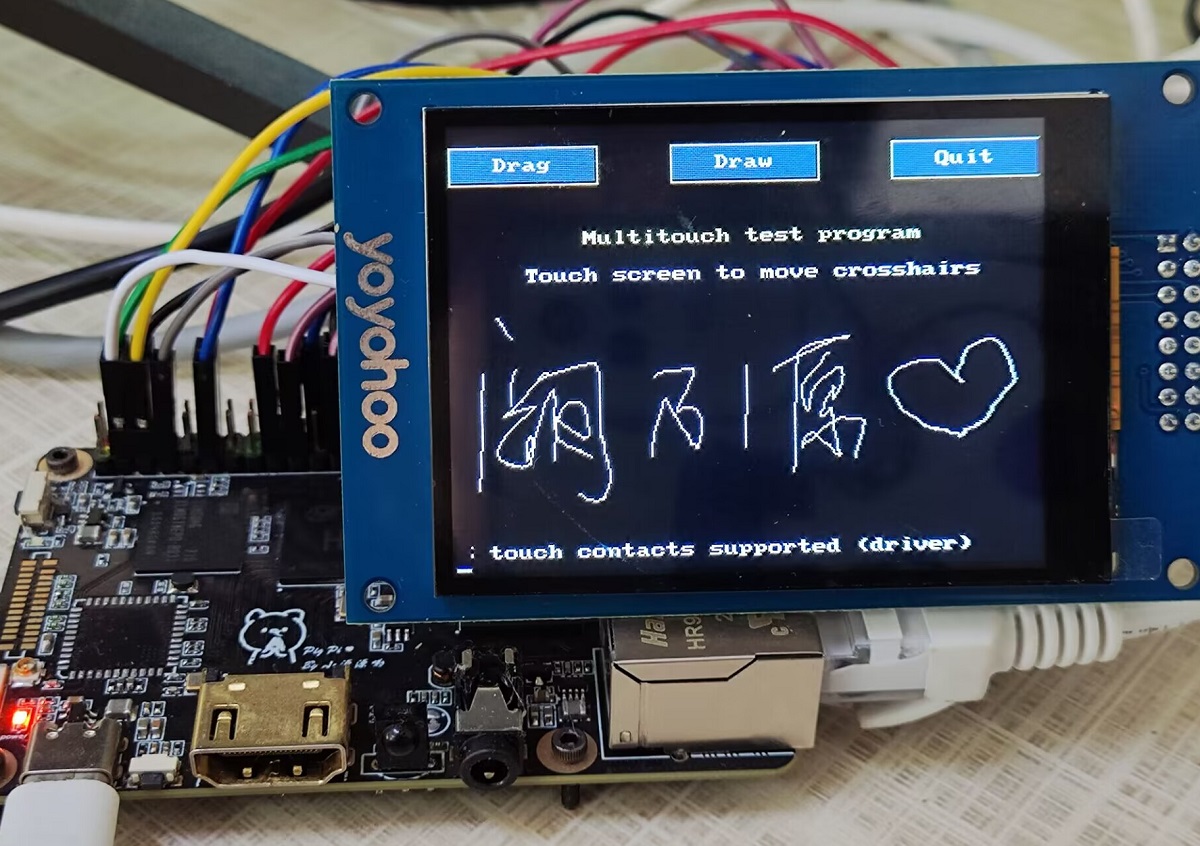
至此,从头写GT911触摸驱动就圆满完成了!